Contact
Write to Us And We Would Be Happy to Advise You.
Do you have any questions, or would you like to speak directly with a representative?
By peter
If you’re looking for a way to control multiple buttons with your Arduino, a button matrix might be just what you need. A button matrix allows you to connect multiple buttons to a single set of pins on your Arduino, saving valuable pins for other uses. One of the most common button matrix configurations is the 4×4 matrix, which allows you to connect up to 16 buttons using only 8 pins on your Arduino.

To use a 4×4 button matrix with your Arduino, you’ll need to connect the matrix to your Arduino’s digital pins and use a library to read the button presses. There are several libraries available for this purpose, including the Keypad library, which is included with the Arduino IDE. Once you’ve connected the matrix and installed the library, you can use the library’s functions to detect which button has been pressed.
Using a 4×4 button matrix with your Arduino opens up a wide range of possibilities for controlling your projects. Whether you’re building a game controller, a musical instrument, or a custom input device, a button matrix can help you save valuable pins on your Arduino and simplify your circuit design. With the right library and a little bit of programming, you can easily add a versatile and powerful input system to your Arduino projects.
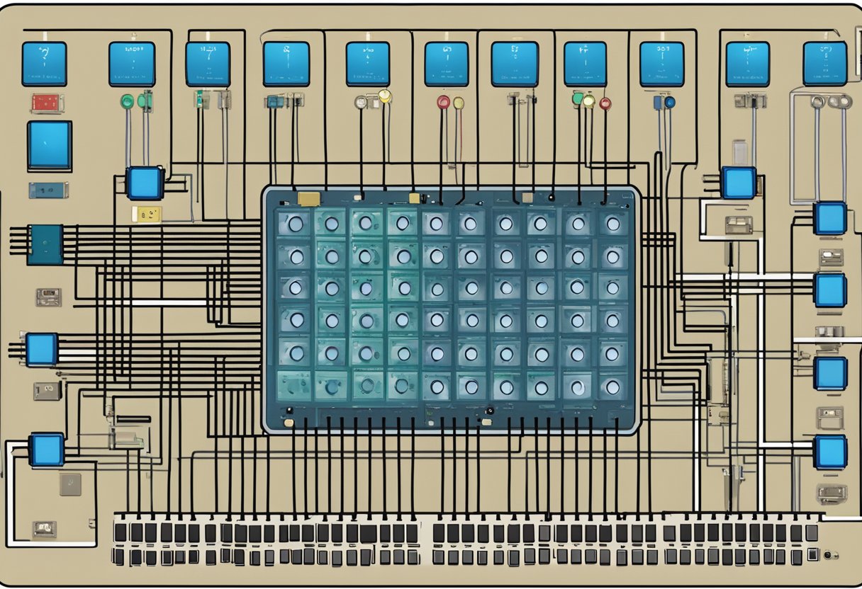
A button matrix is a grid of buttons arranged in rows and columns. The 4×4 button matrix is a common configuration that can be used with an Arduino microcontroller for various projects. Understanding how the button matrix works is essential for designing and implementing an effective system.
The 4×4 button matrix consists of sixteen buttons arranged in a 4×4 grid. The matrix has four rows and four columns. Each button is connected to a unique combination of one row and one column. The rows and columns are connected to the microcontroller’s digital input/output pins.
The UK post code matrix layout and design are crucial to ensure that each button is uniquely identified. The rows and columns are arranged in a way that no two buttons share the same combination of row and column. The layout can be optimized to minimize the number of pins used to connect the matrix to the microcontroller.
The button matrix operation is based on the principle of scanning. The microcontroller scans the rows and columns of the matrix to detect which button is pressed. The scanning process involves setting each row’s digital output pin to HIGH and reading the column’s digital input pins. When a button is pressed, the corresponding row and column are shorted, and the microcontroller detects a logic LOW on the column’s digital input pin.
The scanning process is repeated for each row, and the microcontroller detects which button is pressed based on the combination of row and column that produces a logic LOW. The microcontroller can then execute the appropriate code based on the button pressed.
In conclusion, understanding the layout and operation principles of the 4×4 button matrix is essential for designing and implementing an effective system. By using the scanning principle, the microcontroller can detect which button is pressed and execute the appropriate code.
Before you start integrating the 4×4 button matrix with Arduino, you need to gather the following components:
Once you have all the components, you can start connecting the 4×4 button matrix with the Arduino board. Here’s a step-by-step guide:
#include <Keypad.h>

const byte ROWS = 4; // Four rows
const byte COLS = 4; // Four columns
char keys[ROWS][COLS] = {
  {'1','2','3','A'},
  {'4','5','6','B'},
  {'7','8','9','C'},
  {'*','0','#','D'}
};
byte rowPins[ROWS] = {2, 3, 4, 5}; // Connect to the row pinouts of the keypad
byte colPins[COLS] = {6, 7, 8, 9}; // Connect to the column pinouts of the keypad

Keypad keypad = Keypad(makeKeymap(keys), rowPins, colPins, ROWS, COLS);

void setup() {
  Serial.begin(9600);
}

void loop() {
  char key = keypad.getKey();
  if (key) {
    Serial.println(key);
  }
}
That’s it! You have successfully integrated the 4×4 button matrix with Arduino. You can now use the keypad to input data and control your Arduino projects.
Before you can start programming your Arduino for a button matrix, you need to set up the Arduino IDE. The UK post code Arduino IDE is a software platform that allows you to write and upload code to your Arduino board. You can download the Arduino IDE from the official Arduino website.
Once you have downloaded and installed the Arduino IDE, you need to select the correct board and port. To do this, go to the Tools menu and select Board and then choose your Arduino board. Next, go to the Tools menu again and select Port and then choose the port that your Arduino board is connected to.
To program your Arduino for a button matrix, you need to write code that scans the matrix and detects when a button is pressed. You can use the Keypad library to simplify this process. The Keypad library allows you to define the size and layout of your button matrix and provides functions for scanning the matrix and detecting button presses.
Here is an example code snippet that scans a 4×4 button matrix:
#include <Keypad.h>

const byte ROWS = 4; //four rows
const byte COLS = 4; //four columns
char keys[ROWS][COLS] = {
  {'1','2','3','A'},
  {'4','5','6','B'},
  {'7','8','9','C'},
  {'*','0','#','D'}
};
byte rowPins[ROWS] = {9, 8, 7, 6}; //connect to the row pinouts of the keypad
byte colPins[COLS] = {5, 4, 3, 2}; //connect to the column pinouts of the keypad

Keypad keypad = Keypad( makeKeymap(keys), rowPins, colPins, ROWS, COLS );

void setup(){
  Serial.begin(9600);
}

void loop(){
  char key = keypad.getKey();
  if (key != NO_KEY){
    Serial.println(key);
  }
}
In this example, we define a 4×4 button matrix and specify the pin connections for the rows and columns of the matrix. We then create a Keypad object and pass in the matrix layout and pin connections. Finally, we use the getKey() function to scan the matrix and detect button presses.
One common issue with button matrices is that they can produce multiple button presses when a button is pressed or released. This is known as “bouncing” and can be caused by the physical properties of the button or the electrical properties of the matrix.
To prevent bouncing, you can use a technique called “debouncing”. Debouncing involves adding a delay between button presses to allow the electrical signals to stabilize. You can use the Bounce2 library to simplify this process. The Bounce2 library provides functions for debouncing button presses and releases.
Here is an example code snippet that uses the Bounce2 library to debounce button presses:
#include <Keypad.h>
#include <Bounce2.h>

const byte ROWS = 4; //four rows
const byte COLS = 4; //four columns
char keys[ROWS][COLS] = {
  {'1','2','3','A'},
  {'4','5','6','B'},
  {'7','8','9','C'},
  {'*','0','#','D'}
};
byte rowPins[ROWS] = {9, 8, 7, 6}; //connect to the row pinouts of the keypad
byte colPins[COLS] = {5, 4, 3, 2}; //connect to the column pinouts of the keypad

Keypad keypad = Keypad( makeKeymap(keys), rowPins, colPins, ROWS, COLS );

Bounce debouncer = Bounce();

void setup(){
  Serial.begin(9600);
  debouncer.attach(0, INPUT_PULLUP);
  debouncer.interval(25);
}

void loop(){
  char key = keypad.getKey();
  if (key != NO_KEY){
    debouncer.update();
    if (debouncer.fell()){
      Serial.println(key);
    }
  }
}
In this example, we use the Bounce2 library to debounce button presses. We create a Bounce object and attach it to the pin that the button is connected to. We then use the fell() function to detect when the button is pressed and debounce the signal using the interval() function.
Do you have any questions, or would you like to speak directly with a representative?