Contact
Write to Us And We Would Be Happy to Advise You.
Do you have any questions, or would you like to speak directly with a representative?
By hqt
Membrane switches are a common HMI that are activated and deactivated by the touch of a button. The most critical part is the contact between the line and the shrapnel. Each layer of tape and substrate material in the assembly has its primary purpose, and can be customized for different functions depending on the usage environment and various designs. The design of the membrane switch also needs to follow certain principles to meet its needs.
Graphic Overlay can play the role of indicating, promoting, protecting and improving efficiency. Graphic Overlay is usually screen printing or digital printing products on polyester, polycarbonate and acrylic. The design and appearance of graphics usually require vector documents or customer samples for product design to electronic documents, and then from electronic documents to samples or mass production. But ordinary Graphic Overlay does not have any circuit or wire function. But there will be electrical wiring at the bottom of the graphic overlay in the membrane switch. So let’s introduce the electrical function of the membrane switch.
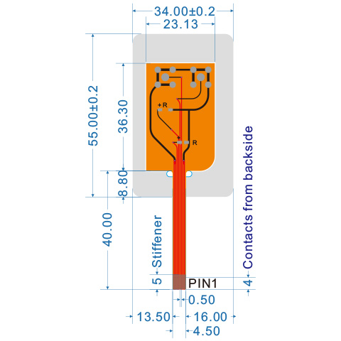
There are three kinds of PET, FPC and PCB for the circuit layer selection of membrane switch. As the choice of screen printing, PET line has been recognized by the market for its low cost and stable performance. If you pursue higher performance stability and FPC and PCB of various components, it is a better choice. The FPC uses a flexible polyamide circuit, using PI, a high-efficiency circuit formed by copper foil corrosion and gold plating. The PCB is FR4 board gold-plated film corrosion and other methods to complete the circuit matrix. For details, please click here to learn more.
Electrical wiring can be routed through additional LEDs, capacitors, resistors or even light sensors. It can also be said that this part is the key part of the electrical function of the membrane switch.
The connector options for membrane switches are also three ZIF, Male and Female connectors.
ZIF connectors are the most common and cheapest way to connect, because there is no need for additional Male and Female connectors and soldering costs. Only simple printing and etching can be done. At the same time, we will also mark each PIN on the customer’s drawing for the customer’s verification and inspection.
Male connectors are generally products that use male terminals, that is, metal pins, to solder on the line. This type of design needs to pay attention to the connection between the Pin pin resistance and the PET circuit.
Do you have any questions, or would you like to speak directly with a representative?