Contact
Write to Us And We Would Be Happy to Advise You.
Do you have any questions, or would you like to speak directly with a representative?
By hqt
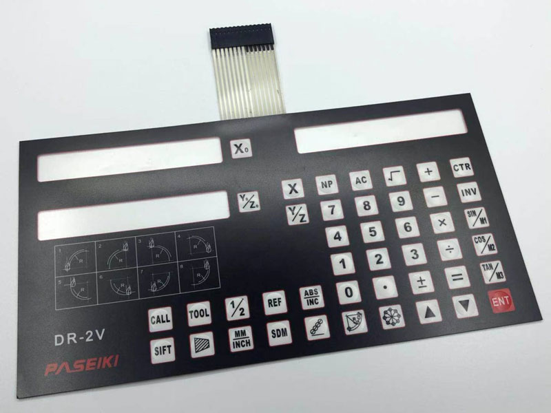
Membrane matrix keypad comes with 16 membrane buttons. The buttons combine in a 4×4 matrix. The keypad consists of buttons in the form of a sealed socket made of rubberized material. The back side comes on a self-adhesive base. Furthermore, this makes it easy to fix the panel.
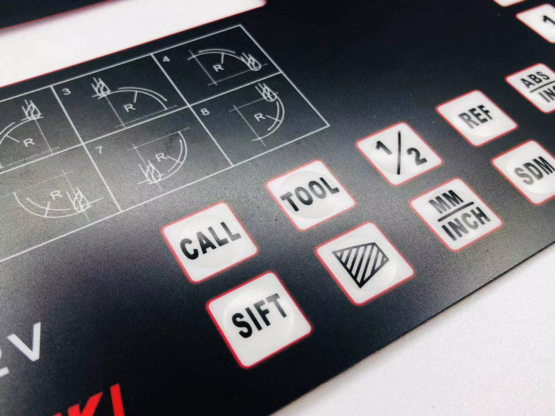
Moreover, the panel bends, so it sticks even on a mug. The keypads seal, flexible and durable. They are not afraid of water, heat and withstand a million clicks.
The keypad comes in the form of a 4×4 matrix. Similarly, each button is an air gap area between two dielectric layers coated with conductive coatings. The tracks of the conductive coating of one layer applies horizontally (pins 1-4), and the other one vertically (pins 5-8).
Pressing the button leads to the connection of the track of one layer with the track of another. As a result, to the closure of one of the pins 1-4 with one of the pins 5-8 also fix here.
Membrane matrix keypad is a great way to let users interact with your project. You can use them to navigate menus, enter passwords, control games and robots.
This article will use a 4×4 matrix membrane keypad – thin and with an adhesive backing – sticks to most flat surfaces. You can buy phone-style keypads with thicker buttons if you like that style, keypads from old push-button phones will also work with the Arduino.
The buttons on the keypad arrange in rows and columns. The 4×4 keypad has 4 rows and 4 columns. Each row (pins 1-4) and column (pins 5-8) connect to one pin, 8 pins in total.
The 4×4 keypad layout shows how rows and columns connect:
Matrix keypad layout 4×4
Pressing the button closes one of pins 1-4 with one of pins 5-8. For example, you can see that the combination of row 3 and column 3 only means that button number 9 presses.
The pinout for most membrane keypads is as follows:
4×4 Matrix Keypad Wiring Diagram for Arduino Uno:
If the location of the membrane matrix keypad contacts does not match the above, you can find the contacts programmatically. To do this, you will need to assemble a test circuit by connecting the LED through a current-limiting resistor to the Arduino (or any 5V power supply) as follows:
Test scheme for finding contacts
First find out which keypad pins are connected to the rows of buttons. Insert the ground (black) wire into the first contact on the left. Press and hold any button on line 1. Insert the positive (red) wire into each of the other pins.
If the LED lights up on one of the pins, press and hold the other button on row 1, then reinsert the positive wire into each of the other pins. Moreover, the LED lights up on the other pin, this means that the ground wire is inserted into the row 1 pin. If none of the buttons in row 1 light up, then the ground wire is not connected to row 1.
Now move the ground wire to the next pin, press the button in another row and repeat the above process until you see the found contact for each row.
To find out which pins the columns connect on membrane matrix keypad, insert a ground wire into the pin you found out is row 1. Now press and hold any of the buttons on that row. Insert a positive wire into each of the remaining pins.
The pin that makes the LED light up is the pin connected to the button’s column. Press another button on the same row and insert a positive wire into each of the other pins. Repeat this process for all other columns until each one has been found.
To demonstrate how it works, let’s print each keystroke on the Arduino IDE ‘s Serial Monitor screen . The sketch will use the keypad library written by Mark Stanley and Alexander Brevig. The functions of the library are to monitor the setup of contacts and the results of polling columns and rows. Similarly, to install the keypad library, go to Manage Libraries and type “keypad” in the search bar.
In the world of electronics, a keypad is a device consisting of individual buttons. Similarly, it allows you to enter information into a computer or other electronic device.
Keypads have a lot of options. Older personal computers used keypads with mechanical keys that had a lot of travel and were almost as comfortable as the keys on old typewriters.
For the past 15-20 years, membrane matrix keypad has been widely common, which are simpler and cheaper to manufacture. It is this keypad that we will connect to Arduino.
The matrix membrane keypad, popular in Arduino projects, has 12 or 16 buttons. A cable comes out from the bottom of the keypad, ending with a dupont socket.
The matrix keypad consists of buttons that form an mxn matrix, i.e. table, where m is the number of rows and n is the number of columns. For the lesson, we will use the 4×3 keypad. If we look at her train, we will see that it consists of 7 tracks. Tracks numbered 1-4 (let’s denote them Row1-Row4) are the first to fourth rows of the matrix, and tracks numbered 5-7 (Col1-Col3) are columns one to three.
Each button is an area of intersection of conductive tracks. When you click on the area denoting the button, the tracks are connected and one of the outputs of rows 1-4 is closed with one of the outputs of columns 1-3.
To display the information entered from the keypad, we will use an LCD display with an I2C interface.
Do you have any questions, or would you like to speak directly with a representative?