Contact
Write to Us And We Would Be Happy to Advise You.
Do you have any questions, or would you like to speak directly with a representative?
By Fariha
Niceone-Keypad’s in-house design studio accepts membrane switch projects at any stage of readiness — a dimensioned sketch, a rough PDF layout, or a physical reference panel is enough to begin. Our engineering team in Dongguan, coordinated through our US office in Redding, Connecticut, converts your concept into three production-ready deliverables: an editable vector overlay file (.ai/.eps), a master dimensional DXF, and a circuit routing schematic with connector pinout. You do not need a specialist HMI designer on your team before contacting us.
This page is written for OEM product engineers and industrial designers who have a panel concept but lack deep membrane switch design experience. If you want a supplier who shares the design work — not one that waits for perfect files — here is exactly how our process works, what we produce, and what we need from you to start.
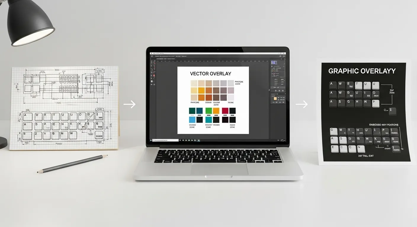
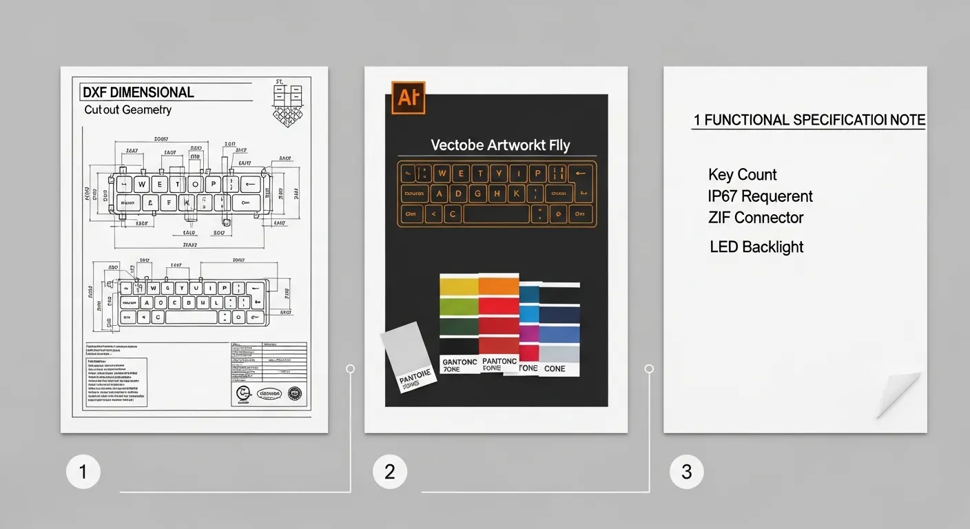
Before a single panel is cut or a circuit is printed, our design team produces three files for your review and approval:
All three files are sent as a design proof before any production begins. Nothing moves forward without your written approval.
For the engineering tolerances and keep-out rules the studio follows when building these files, see our membrane switch engineering design rules.
| What You Send | What Our Studio Produces | Why It Matters at Production |
|---|---|---|
| Sketch, DXF, DWG, or panel sample | Master dimensional DXF with verified cutouts and tail exit | Sets the die-cut master; prevents tooling error |
| Pantone chip, PMS code, or color sample | Editable .ai overlay with named PMS swatches + printed proof | Locks color before any ink is committed to screen |
| Functional spec note (keys, IP req., backlight, connector) | Circuit schematic + IP seal zone engineering note | Prevents connector mismatch and waterproofing failure |
Many buyers stall because they assume the design must be finished before they contact a manufacturer. It does not. Here is the minimum we need — and what we accept at each stage:
File 1 — Dimensional referenceA dimensioned hand sketch, a DWG/DXF, a PDF mechanical drawing, or a physical sample. The critical information: overall panel size, mounting hole positions, and which edge the connector exits from. Approximate dimensions are workable; the studio will flag anything that needs confirmation.
File 2 — Artwork intentA sketch, a reference image with Pantone numbers, a physical color sample, or a rough PDF layout. Vector format (.ai, .eps, .pdf from a native vector program) is preferred. If you send a JPG or PNG screenshot, we will rebuild it as a vector — but color accuracy depends on buyer confirmation at the proof stage, because screen captures carry significant color shift risk.
File 3 — Functional specification noteA single email or a completed RFQ field covering: number of keys, tactile or non-tactile, backlighting requirement (yes/no), IP rating target (if any), and connector preference (ZIF tail, Molex, bare contacts, or “advise me”). This does not need to be a formal document.
Once we receive your three inputs, the studio works through a structured four-step review before sending your proof:
Once the design proof is approved, the project moves directly into prototyping inside the same Dongguan facility. See how that stage works: membrane switch prototype service process.
The Pantone Matching System (PMS) is the studio’s standard color reference for screen-printed graphic overlays. Buyers should supply PMS codes rather than RGB hex values or CMYK breakdowns when screen printing is involved — the ink mixing system is calibrated to PMS, not to digital color profiles.
If you do not have a PMS number, send a physical sample — an existing overlay, a painted metal panel, a plastic housing, or a Pantone chip. The studio will identify the closest PMS match and include it in the design proof. For digital printing, CMYK values are used and confirmed against a calibrated printed proof before the production run.
One critical note: selective textures and hard coats change perceived color. A matte finish shifts apparent lightness compared to a gloss finish, even with the same PMS ink. Confirm your surface finish before approving the final color proof.
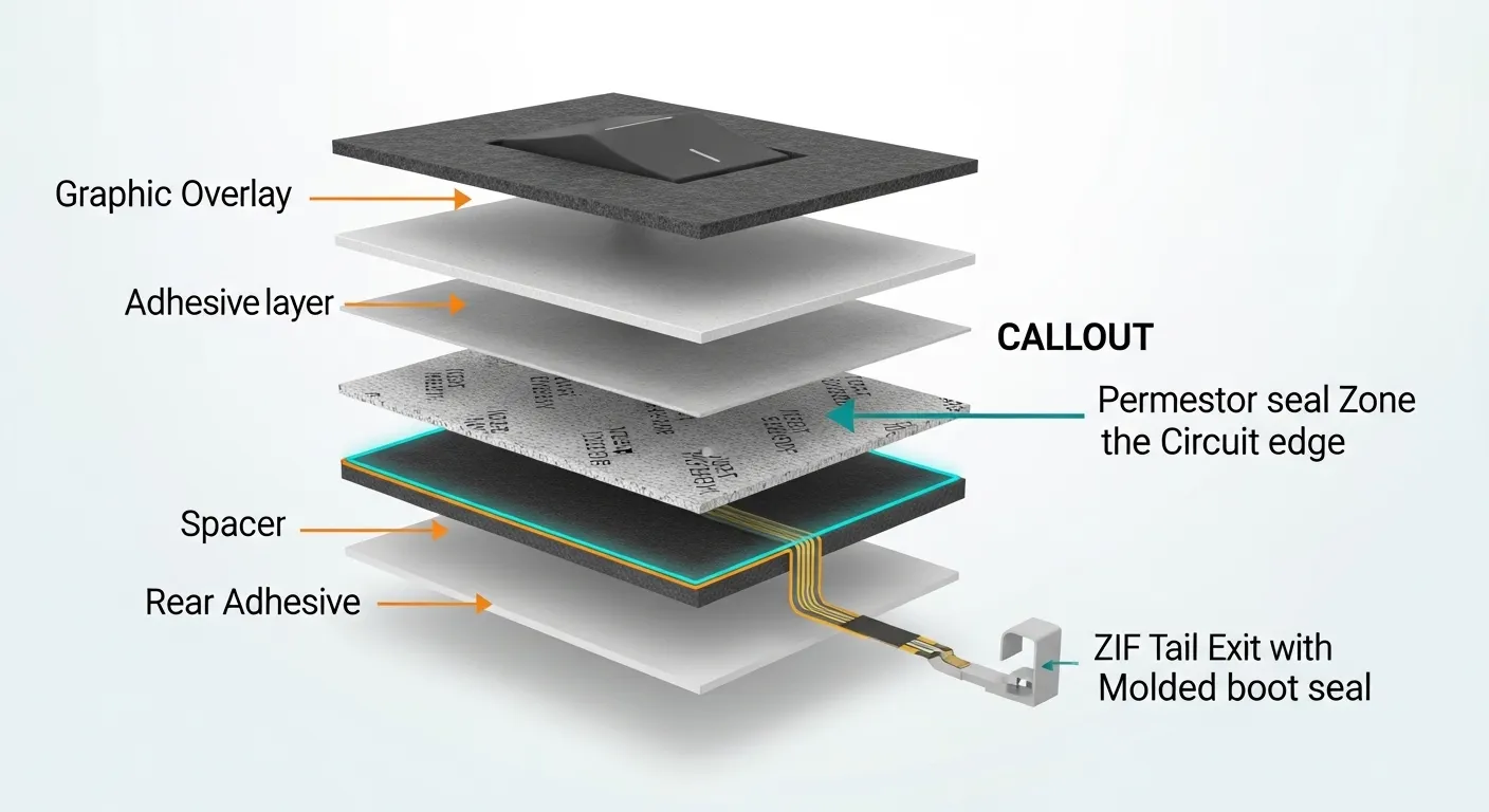
Specifying IP65 or IP67 on an RFQ is not the same as engineering it into the design. IP rating is a geometric and material decision that affects the overlay file, the circuit layout, and the connector exit — our studio handles all of it.
When an IP65 or IP67 requirement is confirmed, the design studio:
Buyers do not need to calculate seal zone dimensions. That is the design studio’s responsibility — you specify the IP target, we engineer the geometry.
The five most common buyer-side errors that trigger expensive respins:
For the full set of engineering tolerances and trace-width rules the studio enforces during layout, see our membrane switch engineering design rules.
Design review timelines depend on input quality and the complexity of the assembly. Projects submitted with a clear dimensional reference, a vector artwork file, and a written functional spec move through the studio faster than projects that require full reconstruction from a sketch.
Our Connecticut office handles English-language design communication — design proofs are reviewed and discussed in US business hours, which eliminates the asynchronous turnaround gap that often adds days to offshore manufacturing projects. Revision requests go directly to the Dongguan design team through our CT project engineers.
Once the design proof is approved, the project moves into prototype production inside the same factory — no file transfer to a third-party toolmaker, no re-specification at a separate supplier. The same engineering team that built the design file oversees the prototype build. Buyers who want to understand that next stage in detail can review the full membrane switch prototype service process.
No. A dimensioned sketch, a physical panel sample, or a rough PDF layout is enough to begin. The studio converts your input into a workable DXF and flags anything that needs clarification before the design proof is built. Most buyers do not have complete files at first contact.
Send .ai (Adobe Illustrator) or .eps for artwork, and DXF or DWG for dimensional drawings. PDF exported from a native vector program is also accepted. Avoid JPG or PNG for artwork — raster files require vector rebuilding and carry color-shift risk that must be resolved at the proof stage.
Include your IP target in the functional spec note (File 3). The design studio engineers the seal zone geometry, adjusts emboss positions, and confirms the tail exit sealing method. You do not need to calculate keep-out dimensions — that is part of the membrane switch design service.
One standard design proof round is included. Additional revision rounds are coordinated through our CT office and discussed with your project engineer based on the scope of changes. Complex layout revisions — circuit rerouting, major dimensional changes — are assessed individually.
Yes. Send a physical sample — an existing overlay, a painted housing, a color chip, or a printed panel. The studio identifies the closest PMS match and includes it in the design proof for your approval. Screen captures and digital color references are not recommended due to color shift risk.
Ready to move your membrane switch concept to a production-ready file? Contact Niceone-Keypad’s design studio with:
Not ready to submit files yet? Contact our US office in Redding, CT to discuss your concept with an English-speaking project engineer before committing to a formal RFQ.
Email: info@niceone-keypad.comUS Office: 18 Dayton Rd, Redding, CT 06896
Send your files and we will return a design review note and proof within our standard turnaround. No finished drawings required to start.
Do you have any questions, or would you like to speak directly with a representative?