Contact
Write to Us And We Would Be Happy to Advise You.
Do you have any questions, or would you like to speak directly with a representative?
By Fariha
Niceone-Keypad designs custom telecom equipment membrane switch assemblies for OEM design engineers who need long-service rack-front HMI panels, tactile keys, stable circuit routing, and project-specific shielding. For telecom equipment makers, the main decision is not only the graphic overlay. It is the full switch stack: dome or contact type, cycle-life target, ESD/RFI shielding, FPC or PCB circuit, connector tail, adhesive, and compliance documentation.
This page is for engineers specifying membrane keypads for network equipment, RF devices, optical transport systems, base-station control units, telecom test instruments, and rack-mounted monitoring panels. Niceone supports custom membrane switches, graphic overlays, membrane panels, capacitive switches, backlighting, FPC, PCB-based membrane switches, and IP-rated constructions from our Dongguan factory, with US-office support in Redding, Connecticut.
If your project requires a 10-million-plus cycle target, shielding review, FCC/CE/RoHS documentation planning, or a prototype-ready RFQ, send drawings and technical requirements for engineering review.
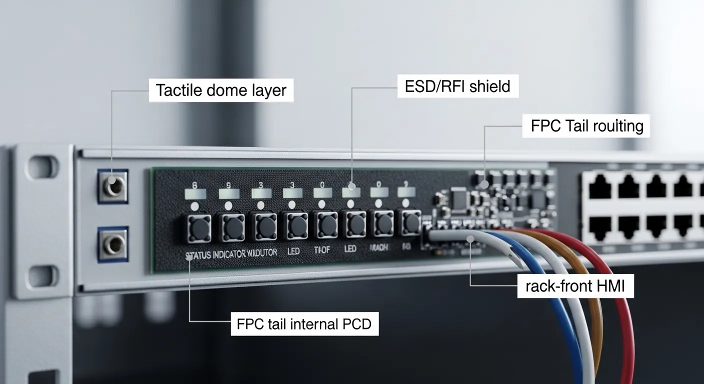
Telecom equipment front panels are often used for service access, reset control, diagnostics, alarm acknowledgement, menu navigation, and local configuration. These keys may sit on a rack unit for years, so the switch design must balance long tactile life with stable electrical performance.
A telecom membrane keypad may include:
For telecom rack-front HMI, the design must also consider the metal enclosure, chassis ground, host PCB location, cable routing, and operator access. A keypad that works on a handheld device may not be the right choice for an RF rack, outdoor cabinet, or high-density network control panel.
A 10-million-plus actuation target should be treated as a design requirement, not a generic promise. The final life depends on dome material, dome geometry, overlay thickness, actuation force, key size, travel, spacer height, operating environment, and validation testing.
For telecom equipment, different keys may need different designs. A power or reset key may be pressed rarely but must feel deliberate. A menu, alarm, or service key may be used more often during installation and maintenance. High-frequency keys need more lifecycle attention than low-use status buttons.
Common options include:
Niceone can review your cycle target, tactile preference, and front-panel layout before prototype. For high-cycle telecom keys, specify the expected use pattern by key, not only the total product life.
Use this matrix as an RFQ planning guide. The final construction should be validated by sample testing and the buyer’s project requirements.
| Target use pattern | Approximate cycle target | Best-fit contact option | Tactile feel | Telecom use case | Design risk to check | RFQ note for Niceone |
|---|---|---|---|---|---|---|
| Rare-use safety or reset key | Low to medium | Metal dome or non-tactile | Firm or deliberate | Reset, service lockout, mode select | Accidental activation, force too light | Specify force target and key guard needs |
| Regular setup and menu control | Medium to high | Metal dome | Crisp snap | Menu, enter, up/down navigation | Dome fatigue, overlay cracking | Share expected press frequency by key |
| High-use alarm or field-service key | High | Metal dome or engineered tactile stack | Consistent snap | Alarm acknowledge, test, local operation | Loss of tactile ratio over time | Request lifecycle validation plan |
| Very high cycle target | 10M+ design target | Project-specific tactile or capacitive design | Depends on construction | Long-life rack-front HMI | Unsupported cycle claim without testing | Define test requirement before prototype |
| Sealed flat panel with minimal wear | Project-specific | Capacitive switch | No mechanical click | Outdoor cabinet, sealed RF control panel | False touch, glove use, grounding | Confirm environment and user interface logic |
The best choice is not always the hardest dome. A telecom panel should be designed around how the operator uses each key, how the enclosure is grounded, and how the switch tail connects to the control board.
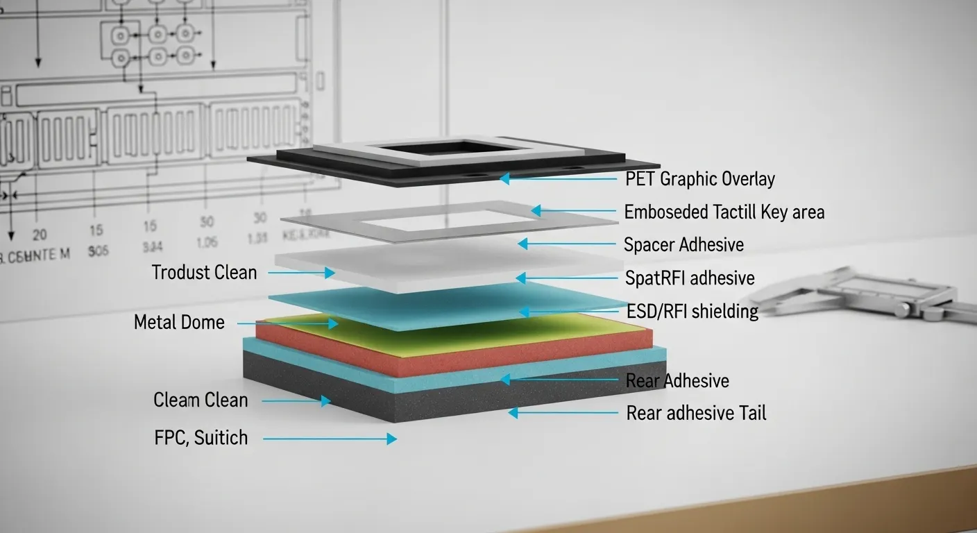
Telecom devices may operate near RF circuits, metal enclosures, grounding systems, and sensitive control electronics. A membrane switch can include ESD, RFI, or EMI shielding, but the shield must be designed into the stack and connected correctly.
Shielding options may include conductive printed layers, carbon or silver shielding, aluminum foil layers, or custom shield traces. The best approach depends on the host device, front-panel construction, target environment, and grounding method.
Before quoting, define:
Do not treat shielding as a checkbox. If the membrane switch shield floats, connects to the wrong location, or routes too close to sensitive lines, the panel may not support the system-level goal. Niceone can review the layer stack and tail routing during RFQ.
Telecom front panels may use a printed PET circuit, flexible printed circuit, or PCB-backed membrane switch. Each option affects cost, routing, thickness, connector choice, and electrical stability.
Printed PET silver circuit works well for many membrane switch layouts. It supports thin construction and flexible tail routing. It is often suitable for simple key matrices and standard front-panel controls.
FPC construction is useful when the design needs finer routing, better dimensional stability, or more robust connection to the host assembly. It can help when the tail is long, folded, or routed through tight enclosure spaces.
PCB-backed membrane switches suit projects that need rigid support, integrated components, connector stability, or a stronger mounting platform. They are often considered when the front panel must align with a rack-mounted control board or support LEDs and components.
Confirm these details before selecting the circuit:
The right circuit choice reduces assembly risk before tooling and sampling.
The graphic overlay is the operator-facing surface, but it also protects the circuit, defines the tactile feel, and supports the brand interface. Telecom panels often need clear legends, durable key areas, and good visibility in service rooms, equipment cabinets, or low-light racks.
Common overlay choices include PET and polycarbonate. PET is often selected for durability and flex performance. Polycarbonate can support a clear graphic appearance, but it should be reviewed for the project’s wear and chemical exposure needs. Hardcoat, matte texture, anti-glare finish, transparent windows, and dead-front icons can also be specified.
Backlighting may be required for alarm areas, status keys, or nighttime maintenance. Options include:
For adhesive, specify the mounting surface. A membrane switch bonded to powder-coated metal, plastic housing, aluminum rack bezels, or stainless panels may need different adhesive selection. If the panel requires IP65 or IP67 sealing, discuss gasket design, edge sealing, tail exit protection, and mounting pressure early.
For telecom equipment, FCC and CE requirements usually apply to the complete device or system, not only the membrane switch. However, the switch design can affect system-level testing through shielding, grounding, cable routing, and material selection.
RoHS planning is more directly connected to the component material stack. Buyers may need material declarations, restricted-substance information, or supplier documentation for export markets.
Before prototyping, clarify:
Niceone should not be asked to guess the compliance band after samples are built. Add documentation needs to the RFQ package so the design team can review them with the stack-up and material plan.
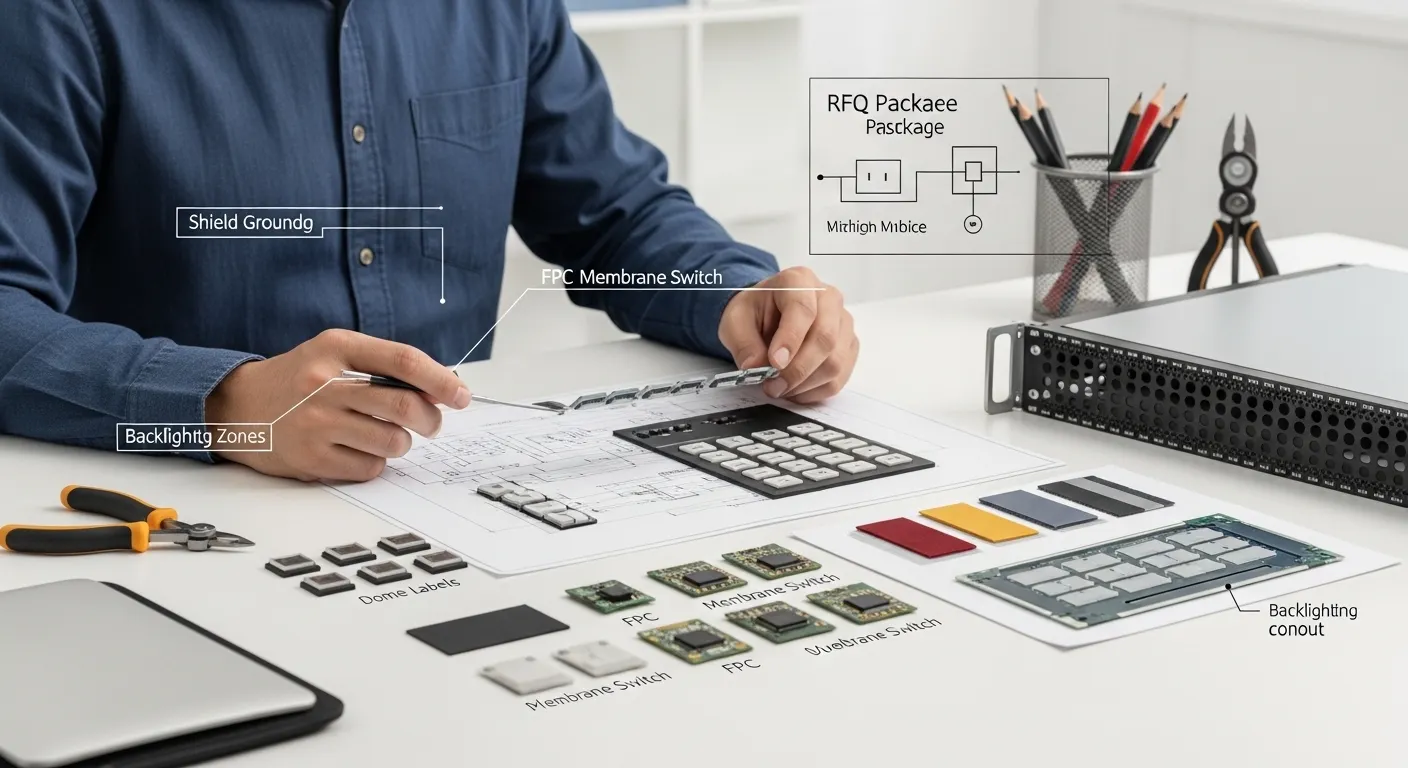
A good RFQ helps engineering respond with the right stack, not just a price. For telecom equipment, include the mechanical, electrical, lifecycle, and compliance details together.
Send these items when available:
If you are unsure about the best construction, send the product use case and available drawings. Niceone can review dome/contact options, shield routing, adhesive selection, and connector direction before sample build.
Yes, it can be specified as a design target. The actual result depends on dome/contact type, force, overlay stack, key size, travel, environment, and testing. Treat 10M+ as a project requirement to validate, not a generic guarantee.
Metal domes are common when the engineer wants crisp tactile feedback. Polydomes, non-tactile contacts, or capacitive switches may fit softer, flatter, or sealed interfaces. The best choice depends on cycle target and user feel.
A shield layer can be added inside the membrane stack using conductive ink, foil, or custom shield traces. It must be routed and grounded correctly to the chassis or PCB to support the equipment-level design.
PET circuits fit many simple keypads. FPC helps with flexible routing and tighter layouts. PCB-backed switches support rigid mounting, connectors, LEDs, or component integration. Choose based on enclosure space and host PCB design.
They can support projects that require related documentation and design review. RoHS often relates to materials. FCC and CE are usually system-level requirements, so shielding, grounding, and cable routing should be planned early.
Send drawings, artwork, button layout, cycle target, circuit diagram, connector/pinout, tail direction, shielding requirement, IP target, compliance documentation needs, and sample quantity. More detail helps reduce redesign before prototyping.
Send your telecom front-panel drawings, rack or enclosure dimensions, button layout, cycle-life target, dome/contact preference, FPC or PCB requirements, connector pinout, ESD/RFI shielding needs, backlighting details, and FCC/CE/RoHS documentation requirements.
Niceone-Keypad can review your telecom equipment membrane switch stack from our Dongguan factory team, with support available through our Redding, Connecticut office for US-based communication and project coordination.
Do you have any questions, or would you like to speak directly with a representative?